Web in this post, we will have a detailed look at dc motor starters and circuit diagram. This one is an 'inboard' type in which the bendix gear throws the pinion towards the motor;
All Types Of Electrical Starter Wiring Diagram Pdf Home Wiring Diagram
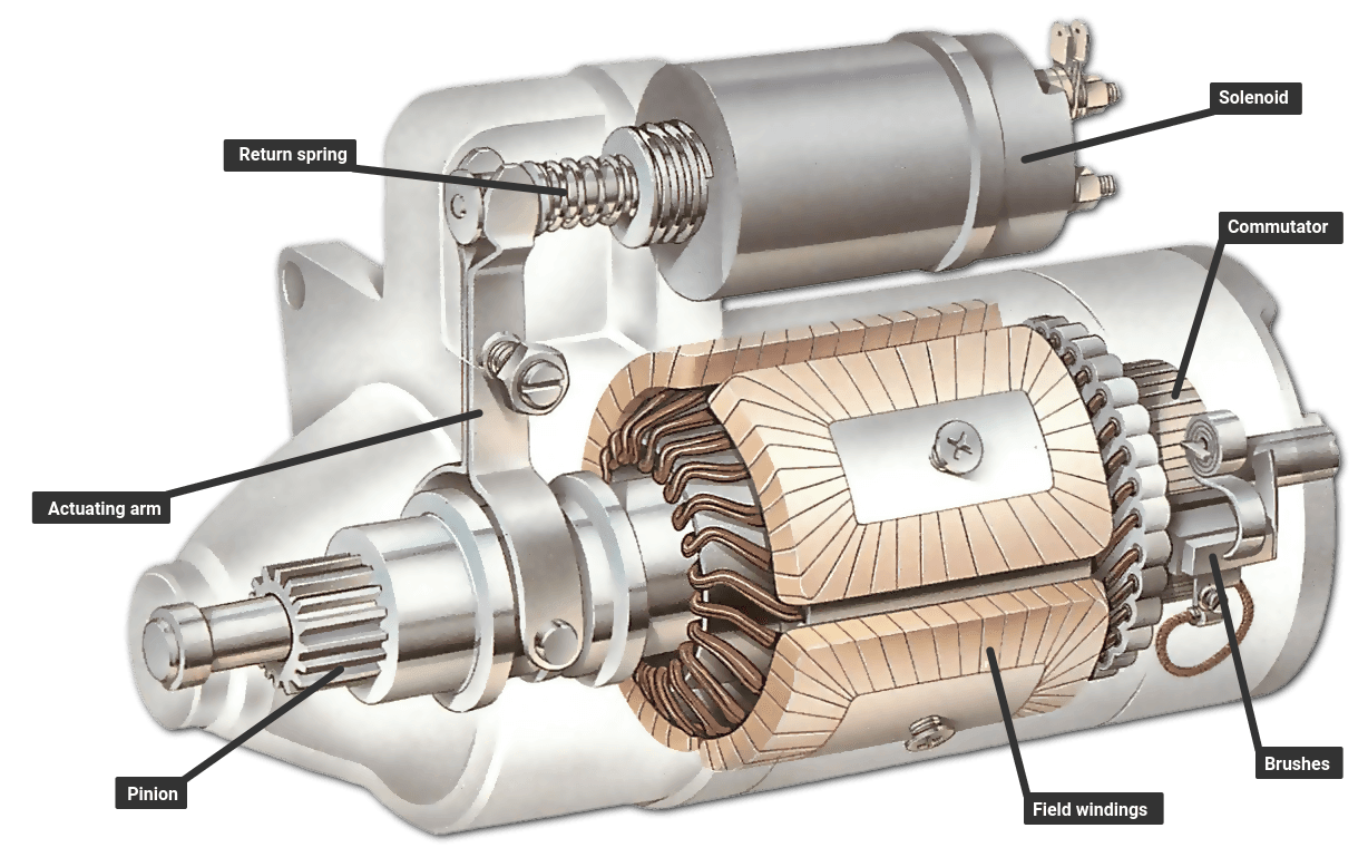
Starter Motor Circuit Diagram. Web a starter motor diagram is a visual representation of a car’s starter motor assembly, outlining various parts of starting system including the starter wiring, and starter control circuit. The main components of a starter motor include the starter motor housing, starter relay, starter motor gear, soft iron core, two coils of wire, and four fields. Web car starter motor control circuit diagram.
Pressing The Start Button Completes A Circuit From L3 Through The Normally Closed Stop Button To Coil K1/4 And The Overload To L2.
There are two circuits to a starter — the power circuit and the control circuit. A direct online starter consists of two buttons, a green button for starting and a red for stopping purpose of the motor. Web inertia system an inertia type starter:
Web Motor Contactor (Or “Starter”) Coils Are Typically Designated By The Letter “M” In Ladder Logic Diagrams.
Web motor contactor (or “starter”) coils are typically designated by the letter “m” in ladder logic diagrams. Circuit diagram and working principle direct online starter is method of starting of an induction motor. The starting motor is mounted on the engine flywheel housing.
Web The Main Function Of Car Starting Circuit Is Using The Small Current From The Car Battery To Control The Large Current Of The Car Starting Circuit, Thus To Start The Starter Motor And Power The Engine.
Loads must be connected in parallel when more than one load must be connected in the line diagram. Web what are the key components of a starter motor, and how do they work together? The soft starter offers a gradual increase in the voltage during the motor startup.
Web A Starter Motor Or Starting Motor, Or Cranking Motor, Is A Direct Current Motor That Cranks The Engine For Starting.
This one is an 'inboard' type in which the bendix gear throws the pinion towards the motor; We are happy to explain further or talk about custom options if you don’t. There are three main components in the switch starting circuit:
It Is The Power Circuit That Passes Electric.
Web direct online starter (dol motor starter): Web a starter motor diagram is a visual representation of a car’s starter motor assembly, outlining various parts of starting system including the starter wiring, and starter control circuit. The stator of the motor receives the full supply voltage in dol starter.
These Symbols Tell Us Where The Connection Needs To Be Made Between The.
Dc motor is a device that uses dc power for the creation of mechanical power. We prefer a direct online starter for starting of small rating three phase induction motors. Web diagram of a resting and spinning starter motor | image source:
Web First Check The Battery And Its Terminals (See Checking The Batteries )And The Other End Of Its Earth Strap.
There are also 'outboard' ones in which it moves the other way. Ignition switch, starter solenoid, starter relay. There are numerous types of dc motor such as shunt.
One For The Positive Battery Cable And The Other For The Thick Wire That Powers The Starter Motor Itself (See The Diagram Below).
Web the voltage from l1 and l2 appears across each load for the proper operation of the pilot light and solenoid. Web the wiring diagram for a dol stater is shown below. The “s” terminal links with the ignition switch circuit.
This Circuit Has Two Lines, One For The Pilot Light And One For The Solenoid.
Web a typical starter solenoid has one small connector for the starter control wire (the white connector in the photo) and two large terminals: The starter motor is mounted on the engine casing and a pinion on the end of the. Every component in the system will be represented by a symbol.
We Will Use A Contactor, An Auxiliary Contact Block, An Overload Relay, A Normally Open Start Pushbutton, A Normally Closed Stop Pushbutton, And A Power Supply With A Fuse.
Web wiring diagrams for the various configurations are below. The main components of a starter motor include the starter motor housing, starter relay, starter motor gear, soft iron core, two coils of wire, and four fields. Web figure 1 contactor circuit diagram for dol starting circuit operation 1.
Web Car Starter Motor Control Circuit Diagram.
Use the circuit tester or test lamp to find if electric current is reaching the solenoid. Web in this post, we will have a detailed look at dc motor starters and circuit diagram. A starter motor is required to run the internal combustion engine up to a speed sufficient to produce satisfactory carburation.
Both Designs Operate In A Similar Manner:
In conclusion, the 3 pole circuit diagram for the starter solenoid provides a clear and concise illustration of how to wire a starter solenoid. Cranking the engine means rotating the crankshaft by applying torque on it so that the piston may get reciprocating motion. The dol starter comprises an mccb or circuit breaker, contactor and an overload relay for protection.
Web The Soft Starter Is A Type Of Motor Starter That Uses The Voltage Reduction Technique To Reduce The Voltage During The Starting Of The Motor.
The electricity that passes through the contacts of the starter, through the overload relay, and out to the motor, is called the power circuit. It is a useful tool for understanding how the starter motor works, identifying issues, and carrying out repairs. If you are unsure, please feel free to contact us.
An Automatic Starter Operates In A Similar Fashion, Except That Automatic Relays Short Out Sections Of The Starter Resistance Either By A Time Sequence Or When The Armature Current Drops To A Selected Value.
Main contactor coil k1/4 then closes and applies full line voltage directly to the motor via contactor contacts k1.1, k1.2 and k1.3. The thick lines of figure 4 represent this power circuit. Figure 4 shows the automatic dc starter circuit diagram.

Chint Dol Starter Wiring Diagram
All Types Of Electrical Starter Wiring Diagram Pdf Home Wiring Diagram

Engine Starter Circuit Currents Bluewater Cruising

Triaging a nocrank condition and testing a starter motor Hagerty Media

Soft Starter Wiring Diagram Pdf Collection Wiring Diagram Sample

Wiring Diagram For Motor Starter Best Diagram Collection

MV Starter Circuits Military Trader/Vehicles

Direct Online Starter (DOL Motor Starter) Circuit Diagram and Working
