Uc3823 high speed pwm controller block diagram prevents the battery from back driving the charger when input power is disconnected. In normal circumstances, the efficiency is 90% and may even go up to 96%.
5V 10A 50W Offline Switching Power Supply Power Supply Circuits
Switch Mode Battery Charger Circuit Diagram. Nickel cadmium and nickel metal hydride nickel cadmium (nicd) batteries have been popular over the last few decades, but they are gradually being replaced with nickel metal hydride (nimh) batteries. 1 3.2 start principle of battery Web in this video i explained china battery charger suoer 12v 30 amp circuit diagram functional description explained.
Web In This Video I Explained China Battery Charger Suoer 12V 30 Amp Circuit Diagram Functional Description Explained.
Both ics provide protection against current and temperature overloads. It can be constructed using bq24105 battery charger controller. The charger that we intent to build here is a two step charger, meaning it will have two charging modes namely constant charge (cc) and constant voltage (cv).
Web Shown Below Is A Schematic For An Sla Battery Charger That Automatically Switches Rate When The Battery Is Fully Charged:
For those applications, the charger of figure 1 delivers 2.5a with efficiency as high as 96%. Input surge and smps fault protection Web cc and cv mode for battery charger:
Driver Circuit Or Main Switcher Ic;
Each method has its advantages and disadvantages. Input surge and fault protection; A simplified circuit for a nonsynchronous buck converter is shown in fig.
By Combining These Two Modes We Will Be Able To Charge The Battery Faster Than Usual.
Web the parts in the dotted box a constitute the battery starting and shutdown circuit; The dotted box b is the battery charging linear voltage regulated circuit; Using a peak voltage detection point of 1.5 v/cell will result in charging to about 97% of full capacity for nimh and nicd batteries.
Block Diagram Of Simple Constant Current Regulator Battery Charging Circuit.
Control circuit power is supplied from an emitter follower off a zener shunt regulator. Web by definition, a switch mode power supply (smps) is a type of power supply that uses semiconductor switching techniques, rather than standard linear methods to provide the required output voltage. 1 3.2 start principle of battery
It Is Implemented By Using The Adjustable Voltage Regulator Lm317.
Web the auto cut off is the most important parameter of the battery charging. A switch mode for lead acid battery charger can be constructed using bq24105 battery charger controller. It can charge a battery of one to six cells
Web Notebook Computers Increasingly Require Complex Battery Charging Algorithms And Systems.
The basic switching converter consists of a power switching stage and a control circuit. Voltage is sensed using a voltage divider directly on the output switching power supply. The dotted box c is the electronic switching circuit, and the dotted box d is the battery charging current limiting circuit.
Web More Efficient Lead Acid Battery Charger Can Be Implemented Using Switch Mode Circuit.
Uc3823 high speed pwm controller block diagram prevents the battery from back driving the charger when input power is disconnected. Current is sensed by current transformer tr2. Nickel cadmium and nickel metal hydride nickel cadmium (nicd) batteries have been popular over the last few decades, but they are gradually being replaced with nickel metal hydride (nimh) batteries.
Web Peak Voltage Detection Is Used In The Constant Current Regulator (Ccr) Battery Charging Circuit Shown Below.
How to repair smps switch mode power supply battery charger 12 volt 30 ampere. Web there are three methods to charging li+ batteries: It provides a regulated charging current and a regulated voltage with only a ±0.8% total voltage error at the battery terminals.
Web Switch Mode Circuits Can Implement The Lead Acid Battery Charger With A More Efficient.
In normal circumstances, the efficiency is 90% and may even go up to 96%.

switch mode power supply Problem Understanding circuit of 5volt
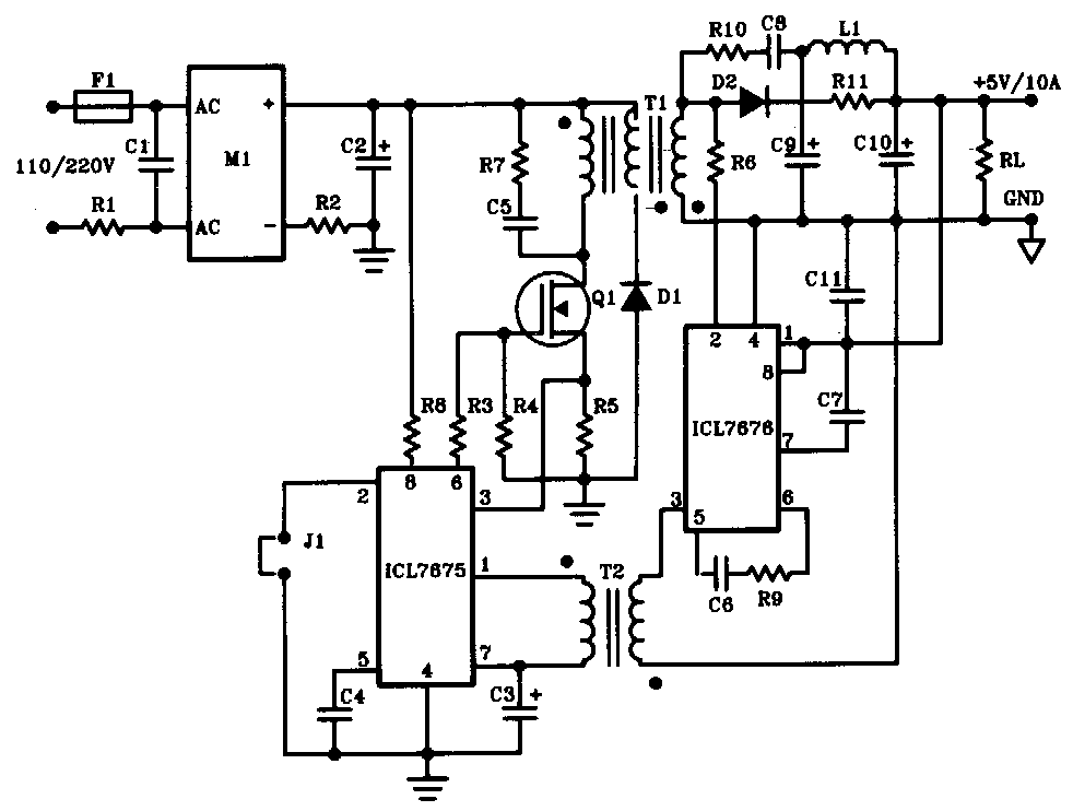
5V 10A 50W Offline Switching Power Supply Power Supply Circuits

replace 1 component to fix switch mode battery charger 12v 10amp

Self Regulating Lead Acid Battery Charger Circuit

Transformerless Battery Charger Circuit 12V, 5 Amp SMPS Based

12 Volt Dc Battery Charger Circuit Diagram

Battery Charger Circuit for 12V & 6V Batteries

12V Automatic Battery Charger Circuit with 4 LED Indicator Homemade
